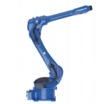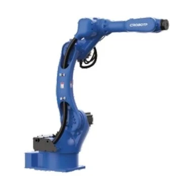
Product Overview
The Pipe / Tube Laser Welding Robot automates laser welding for tubular metal components, including circumferential seams, pipe-to-flange connections, and intersecting tube joints. Its six-axis motion provides flexible access to different weld positions, while coordinated workpiece positioning helps maintain the required relationship between the welding head and the joint.
For manufacturers producing pipes, fittings, and tubular assemblies in batches, robotic laser welding offers programmable weld paths and repeatable motion. The cell layout can be adapted to the component geometry, joint accessibility, laser process, and production sequence.
Key Features
Circumferential and Pipe-to-Flange Welding
Programmed robot motion follows weld paths around pipe ends, cylindrical components, and pipe-to-flange joints. Depending on the part geometry and required weld coverage, the workpiece can remain stationary while the robot follows the seam, or a rotary positioner can turn the part to maintain a suitable welding position.
Access to Angled and Intersecting Tube Joints
The six-axis structure provides flexibility when approaching welds on elbows, branch connections, and tubular assemblies with different joint orientations. Robot positioning and fixture design must provide adequate clearance for the laser welding head and associated process equipment.
Coordinated Laser and Wire-Feeding Functions
Laser-related control functions include power adjustment, pre-emission and power decay, and soft start/stop. Welding interfaces also support functions such as wire-sticking detection, pre-wire extraction, and wire replenishment, along with servo or stepper wire-feeder control where filler wire is required.
Repeatable Motion for Batch Production
Programmed robot paths provide consistent movement across repeated production cycles. The selected laser welding robot platform offers repeatability of ±0.02 mm. Actual weld quality also depends on joint preparation, component tolerances, fixture repeatability, process parameters, and thermal effects.
Technical Specifications
Robot Motion and Working Range
|
Parameter |
Specification |
|
Maximum payload |
12 kg |
|
Maximum reach |
1,510 mm |
|
Number of axes |
6 |
|
Repeatability |
±0.02 mm |
|
J1 axis range |
−167° to +167° for floor/inverted mounting; wall-mounting angle −30° to +30° |
|
J2 axis range |
−155° to +90° |
|
J3 axis range |
−85° to +155° |
|
J4 axis range |
−190° to +190° |
|
J5 axis range |
−105° to +130° |
|
J6 axis range |
−210° to +210° |
Maximum Joint Speed
|
Axis |
Maximum Speed |
|
J1 |
169°/s |
|
J2 |
169°/s |
|
J3 |
169°/s |
|
J4 |
301°/s |
|
J5 |
220°/s |
|
J6 |
743°/s |
Wrist Load Limits
|
Parameter |
J4 |
J5 |
J6 |
|
Allowable torque |
20 N·m |
20 N·m |
11 N·m |
|
Permissible moment of inertia |
0.5 kg·m² |
0.5 kg·m² |
0.16 kg·m² |
Installation and Operating Environment
|
Parameter |
Specification |
|
Mounting orientations |
Floor, inverted, or side mounting |
|
Operating temperature |
0–45°C |
|
Relative humidity |
20–80%, non-condensing |
|
Robot body protection |
IP54 |
|
Wrist protection |
IP67 |
|
Robot weight |
170 kg |
|
Robot body interface |
16-pin interface |
|
Reserved gas connections |
2 × Φ8 mm |
Laser Welding Control and Interfaces
|
Parameter |
Specification |
|
Laser control |
Laser power control, pre-emission and power decay, soft start/stop |
|
Wire-feeding functions |
Wire-sticking detection, pre-wire extraction, wire replenishment |
|
Feeder control |
Servo or stepper wire-feeder control |
|
Control cabinet |
Compact G5A cabinet |
|
Teaching pendant |
Vertical teaching pendant |
|
Power supply |
Single-phase 220 V |
|
Power interruption support |
Built-in UPS |
Applications
The robot is suited to automated laser welding of tubular components where weld-path access, positioning, and repeatable production are important.
- Pipe-to-flange connections
- Circumferential welds on tube ends and cylindrical assemblies
- Elbows and intersecting branch-pipe joints
- Tubular brackets, supports, and metal subassemblies
- Automotive and industrial tubular components
- Automated production cells for fabricated pipe and tube assemblies
Circumferential Weld Planning
For pipe and tube laser welding, the positioning strategy affects robot access, weld-path programming, and production flow. The key decision is whether the robot can follow the required seam around a stationary workpiece or whether a rotary positioner is needed to turn the part through the weld.
- Circumferential joints: Determine how the welding head will access the full seam and whether workpiece rotation is required.
- Pipe-to-flange and branch joints: Check approach angles, nearby obstructions, and clearance around intersecting components.
- Part location: Establish how pipes and fittings will be clamped to keep the joint aligned with the programmed path.
- Production sequence: Include clamping, repositioning, welding, and part changeover when assessing the overall cycle time.
This planning establishes the robot's working arrangement and identifies the peripheral equipment needed for the intended application.
Discuss Your Pipe and Tube Welding Project
Pre-Production Laser Welding Evaluation
The proposed laser welding process needs to suit the actual workpiece and joint before the cell enters production. CRP's process technology laboratory provides sampling, testing, and validation services to support application evaluation.
A practical evaluation examines:
- Material and joint preparation: Whether the material, wall thickness, joint geometry, and fit-up suit the intended laser welding process.
- Weld accessibility: Whether the welding head can reach the complete seam without interference from the part or fixture.
- Positioning repeatability: Whether the selected clamping and positioning method presents the joint consistently across production cycles.
- Process results: Whether sample welds meet the project's specified acceptance criteria before the cell layout is finalized.
Part drawings, joint details, material information, and representative samples provide a useful starting point for evaluating the welding approach and production layout.
FAQ
Q: What information is needed to evaluate a pipe or tube laser welding project?
A: Provide part drawings or 3D models, material and wall-thickness details, joint drawings, required weld locations, and expected production volume. Representative samples and weld acceptance criteria also help evaluate process feasibility and cell layout.
Q: When is a robotic welding cell preferable to a dedicated tube-welding machine?
A: A robotic cell is worth considering when production involves different joint orientations, fittings, or part variants that benefit from programmable motion. A dedicated machine may be better suited to a highly standardized component and a narrowly defined process. Compare part variety, changeover, loading method, cycle time, and weld requirements.
Q: What determines the cycle time of a robotic tube-welding cell?
A: Cycle time depends on weld length, laser process speed, the number of joints, robot movement, rotary positioning, fixture clamping, and part loading and unloading. Robot joint speed alone does not indicate finished-part throughput.
Q: How can one cell handle different pipe sizes and fitting designs?
A: A multi-variant cell typically requires suitable fixtures or adjustable workholding, validated robot programs for each part type, and a repeatable part-location method. The practical range depends on dimensional differences, joint positions, welding-head clearance, and changeover time.
Hot Tags: pipe / tube laser welding robot, China pipe / tube laser welding robot manufacturers, suppliers, factory