Product Overview
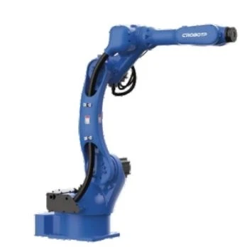
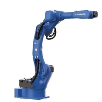
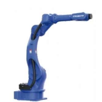
The Vision-Guided Laser Welding Robot is designed for automated laser welding tasks where workpiece positions and weld joint locations may vary. By combining robotic motion with visual guidance and laser process control, it helps manufacturers build more flexible welding cells for complex parts and changing production requirements.
Key Features
Vision-Based Weld Seam Detection and Positioning
The vision system identifies workpiece features and weld joint locations to help align the robot's welding path with the actual part position. This supports automated welding when workpieces are not placed in exactly the same position for every cycle, reducing reliance on precise manual loading.
Adaptive Weld Path Correction and Seam Tracking
Vision-guided path adjustment compensates for differences between the expected workpiece position and its actual location. Real-time seam-tracking functions help the robot follow the detected weld joint during welding, supporting more consistent processing when part positioning or seam location varies.
3D Workpiece Scanning and Path Planning
Three-dimensional vision captures workpiece geometry and provides spatial information for weld path planning. This is useful for parts with complex contours, multiple weld locations, or changing joint positions, helping reduce the amount of manual point-by-point teaching required for suitable applications.
Dedicated Laser Welding Process Control
The robot control system supports laser power control, wire feeding, soft start and stop, pre-emission and power decay, wire-sticking detection, wire pre-extraction, and wire replenishment. These functions help coordinate the welding sequence and filler-wire operations.
Six-Axis Motion for Complex Weld Access
Six-axis movement allows the robot to approach weld joints from different directions and follow varied welding trajectories. A 1,821 mm working radius and 20 kg payload provide flexibility when arranging the robot, workpiece fixtures, welding head, and peripheral equipment.
Repeatable Motion and Flexible Wire Feeding
With a specified repeatability of ±0.05 mm, the robot supports repeatable positioning along programmed welding paths. The system can control servo or stepper motor wire feeders, providing options for integrating wire-feeding equipment into different welding setups.
Technical Specifications
Robot Performance
|
Parameter |
Specification |
|
Number of Axes |
6 |
|
Maximum Payload |
20 kg |
|
Maximum Working Radius |
1,821 mm |
|
Repeatability |
±0.05 mm |
|
Mounting Options |
Floor, inverted, side |
|
Robot Body Protection |
IP54 |
|
Wrist Protection |
IP67 |
|
Robot Weight |
288 kg |
Joint Motion Parameters
|
Axis |
Maximum Motion Range |
Maximum Speed |
|
J1 |
Floor/inverted: -165° to +165°; wall mounting: -30° to +30° |
160°/s |
|
J2 |
-155° to +105° |
160°/s |
|
J3 |
-90° to +135° |
169°/s |
|
J4 |
-190° to +190° |
301°/s |
|
J5 |
-90° to +110° |
342°/s |
|
J6 |
-210° to +210° |
708°/s |
Wrist Load Parameters
|
Parameter |
J4 |
J5 |
J6 |
|
Allowable Torque |
55 N·m |
55 N·m |
24 N·m |
|
Permissible Moment of Inertia |
2.1 kg·m² |
2.1 kg·m² |
0.16 kg·m² |
Operating Environment and Connections
|
Parameter |
Specification |
|
Ambient Temperature |
0–45°C |
|
Relative Humidity |
20–80% RH, non-condensing |
|
Body Interface |
16-pin; 2 × Φ8 mm |
|
Electrical Cabinet Input |
Single-phase 220 V |
|
Power Backup |
Built-in UPS |
|
External Axes |
2 optional external axes |
Applications
The Vision-Guided Laser Welding Robot is suited to automated metal joining tasks where accurate seam location, flexible path generation, or compensation for workpiece-position variation is important.
- Sheet Metal Assemblies: Locate and follow weld joints on fabricated sheet metal parts.
- Automotive Components: Support automated welding of metal components with repeatable joint features and variable part positioning.
- Metal Enclosures and Housings: Handle weld paths around edges, corners, and other defined joint geometries.
- Precision Metal Parts: Apply vision-guided positioning where weld locations must align with the actual workpiece.
- Complex Contoured Workpieces: Use 3D scanning and path planning for suitable parts with non-linear seams or multiple weld locations.
- Flexible Automated Welding Cells: Integrate robot motion, visual guidance, laser welding control, and wire feeding into a coordinated production setup.
Customization and Integration
The system can be adapted to different production layouts and welding tasks through the selection and arrangement of vision equipment, laser welding components, wire-feeding devices, fixtures, and optional external axes.
Integration planning should consider:
- Workpiece drawings, dimensions, and joint geometry
- Required seam detection and tracking method
- Laser source and welding head requirements
- Wire-feeding method, where applicable
- Workpiece positioning and fixture design
- Robot access, cycle sequence, and surrounding equipment
Why Choose CRP Robot
- Robot Manufacturing Capability: CRP Robot has a manufacturing base exceeding 30,000 m² and an annual robot production capacity of 30,000 sets, supporting industrial robot supply for automation projects.
- In-House R&D and Production: Dedicated R&D resources and in-house component manufacturing support robot development and system integration requirements.
- Quality Control: Quality checks cover incoming materials, manufacturing, assembly, and pre-shipment stages. Robot testing includes repeat-positioning and load-stability checks.
- Integration and Technical Support: CRP provides project support for robot applications, with onsite support and service resources available for relevant automation requirements.
FAQ
Q: How does vision guidance differ from conventional robot teaching?
A: Conventional robot teaching generally relies on programmed positions based on an expected workpiece location. Vision guidance uses visual information to identify workpiece features and weld joint positions, allowing the robot path to be generated or adjusted according to the detected part. This is particularly useful when workpiece placement varies or when parts have complex weld geometries.
Q: What is the difference between weld seam finding and real-time seam tracking?
A: Weld seam finding identifies the seam location before welding so the robot can establish an appropriate path. Real-time seam tracking monitors seam position during welding and adjusts the robot's movement to follow detected changes. Both functions help address positioning variation, but they operate at different stages of the welding process.
Q: Can the system handle workpieces with different geometries?
A: The system can support different workpiece geometries through vision-based positioning, 3D scanning, and path planning. The practical range depends on the available vision field, robot reach, welding access, fixture arrangement, and the complexity of the required paths. Parts with significantly different geometries may require separate scanning procedures or welding programs.
Q: What information is useful when planning a vision-guided laser welding cell?
A: Workpiece drawings or 3D models, material and thickness, joint type, weld locations, production volume, fixture layout, and existing laser equipment are useful starting points. Sample workpieces and information about allowable part-position variation can also help determine the appropriate vision method and cell layout.
Hot Tags: vision-guided laser welding robot, China vision-guided laser welding robot manufacturers, suppliers, factory